Posts

Radiation

Image
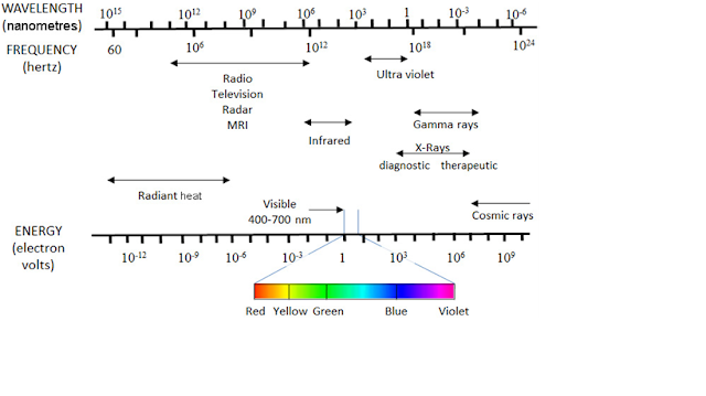
Radiation is the emission or transmission of energy in the form of waves or particles through space or through a material medium. Electromagnetic radiation Electromagnetic waves can, like all waves, be characterized by their amplitude, wavelength ( λ ), frequency ( ν ) and speed. The amplitude is the intensity of the wave. The wavelength is the distance between identical points on adjacent cycles. The frequency is the number of complete wave oscillations per unit time. The speed of the wave is equal to the product of the frequency and the wavelength, and its magnitude depends upon the nature of the material through which the wave travels and the frequency of the radiation. In a vacuum, however, the speed for all electromagnetic waves is a constant, usually denoted by c , and  in which case: c = λν For X rays, wavelength is usually expressed in nanometres (nm) (1 nm =  10 -9  m) and frequency is expressed in Hertz (Hz) (1 Hz = 1 cycle/s = 1 s–1). Whe

Relaxation

Image
Relaxation MRI image contrast is influenced by several characteristics of tissues and other materials including: T1, T2 and T2* relaxation as well as spin density, susceptibility effects and flow effects. This page and the following detailed pages on relaxation parameters will introduce properties and effects on imaging contrast, time and signal-to-noise ratio (SNR). Relaxation  is the process in which spins release the energy received from a radiofrequency pulse. T1 and T2 relaxation rates affect the SNR in an image. Improvement in the SNR is seen when the TR is increased significantly to about 3-5 T1 times. Changing the TR time will also affect the T1 weighting of the image and the acquisition time. T1 weighting occurs in a short TR spin echo sequence because of incomplete recovery of longitudinal magnetization. The effect of TR on SNR can be shown graphically by a T1 relaxation curve as illustrated in the exponential growth curve in figure 1. As the TR is increased to

Electromagnetic Induction

Image
Electromagnetic induction Electromagnetic induction  is the induction of electric current via changing magnetic fields.  Magnetic fields  are generated by moving charges (equivalent to electrical current). Ampere’s law or Fleming’s right hand rule determines the magnitude and direction (i.e. clockwise or anti-clockwise) of the magnetic field with respect to the direction of the flow of current. That is, if you point your right thumb in the direction of the current, the magnetic field will follow the curve of your fingers. Changing magnetic fields can induce an electric current. When a magnet is moved in and out of a closed circuit, an oscillating current is produced which ceases the moment the magnet stops moving. This is explained by Faraday’s law of induction. The change in magnetic flux through a closed circuit induces an electromotive force (EMF) in the circuit. The EMF drives a current in the circuit. The laws of electromagnetic induction state that the induced EMF is:

Larmor Frequency

Larmor Frequency The  Larmor frequency  and equation are named after the Irish physicist and mathematician  Joseph Larmor  (1857-1942). Protons and neutrons pair up in nuclei causing the cancellation of their individual angular momentum. All nuclei also have a spin; those with an odd number of protons and/or neutrons will have a property called a magnetic (dipole) moment. Magnetic moment is characterized by its alignment with an external magnetic field analogous to a small bar magnet. These particular nuclei are also called dipoles because they have two poles like the north and south pole of a bar magnet. H-1 and P-31 are examples of nuclei with an unpaired proton. N-14 is an example of a nucleus with both an unpaired proton and neutron. In addition to alignment of nuclei with a magnetic moment, application of an external magnetic field will produce a secondary spin or wobble ( precession ) of nuclei around the main or static magnetic field. The precessional path around the m

Repetition time

Image
Repetition time    The repetition time (TR) is the time from the application of an excitation pulse to the application of the next pulse. It determines how much longitudinal magnetization recovers between each pulse. It is measured in milliseconds.

Flip Angle

Image
FLIP ANGLE    The flip angle is an MRI phenomenon by which the axis of the hydrogen proton shifts from its longitudinal plane (static magnetic field B0)Z axis to its transverse plane XY axis by excitation with the help of radiofrequency (RF) pulses .  A RF pulse is sent in at the precise Larmor frequency in relation to the gyromagnetic ratio and magnetic field strength.

Echo Time

Image
ECHO TIME The echo time (TE) refers to the time between the application of the radiofrequency excitation pulse and the peak of the signal induced in the coil. It is measured in milliseconds. The amount of T2 relaxation is controlled by the TE.